
Turntable Bearing Design Explained
- Mako
- Mar 6
- 6 min read

Updated: Mar 7
Analog Soundware Design Lab for restorers, collectors, and audiophiles

Inverted, Captive, Magnetic, and Hybrid Approaches
Why the main bearing is the heart of a turntable—and how lubrication, tolerances, and thrust-pad materials define noise floor and longevity.
If the cartridge is the microscope of a turntable system, the main bearing is its foundation. Every vibration the stylus retrieves from the groove must travel through the platter and into the bearing assembly. Any microscopic instability, frictional irregularity, or resonance generated there is modulated directly into the signal.
Motor noise can be mitigated, plinths isolated, chassis damped – but a compromised bearing is a fundamental flaw that cannot be disguised. The main bearing is, unequivocally, the mechanical reference point of the entire record playback system. Its function sounds deceptively simple: to support the platter's mass while enabling rotation with extreme concentric accuracy and minimal friction. Achieving this at an audiophile standard, however, is anything but.
Let’s explore why.
_______________________________________________________________________________________
The Turntable Bearing as Mechanical Ground Zero
A turntable bearing must accomplish five things simultaneously:
Maintain precise vertical and radial alignment: The spindle must remain perfectly centered and perpendicular to the record plane.
Support static and dynamic loads without deformation: It must withstand the constant downward force of the platter's weight and the transient forces of stylus drag.
Minimize friction and micro-chatter: Any mechanical resistance translates directly into noise and speed instability.
Control lubricant film stability: A consistent, hydrodynamic film is vital for low friction and wear.
Resist wear over decades: Longevity is paramount for a high-fidelity investment.
In a well-designed system, the bearing defines the noise floor as much as the motor does. Rumble, low-frequency modulation, and subtle pitch instability often trace back not to drive topology—but to bearing geometry and material decisions.
_______________________________________________________________________________________
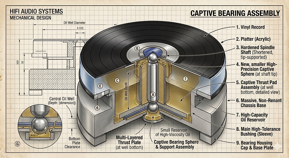
Traditional Captive Bearings (Bottom-Thrust Designs)
The classic “captive” bearing—used in countless vintage designs from Thorens to Linn—positions a hardened steel shaft vertically inside a precision-machined sleeve. The shaft terminates in a point or flat surface resting on a thrust pad at the bottom of the bearing well.
Strengths:
Excellent radial stability when tolerances are tight.
Simplicity of service and lubrication.
Proven longevity when properly maintained.
Challenges:
All axial load is concentrated at the thrust interface.
Wear occurs at a single point of contact.
Lubrication film must remain stable under full platter weight.
In these systems, thrust-pad material becomes critical. Early designs often used phosphor bronze or hardened steel interfaces. Later refinements introduced PTFE, PEEK, Delrin, or carbide pads to reduce friction and control wear.
The sonic signature of a well-executed captive bearing is often described as grounded and stable. However, if tolerances are loose or the lubricant degraded, you may hear increased rumble and a subtle greying of dynamic contrast.
_______________________________________________________________________________________
Inverted Bearings
Inverted bearings reverse the load path: the shaft is fixed to the plinth, and the platter rides on a bearing housing that places the thrust surface at the top rather than the bottom.
You’ll see this architecture in modern high-mass designs from manufacturers such as SME Limited and Clearaudio.
Why invert?
Improved load distribution.
Larger thrust surface area.
Reduced bending moment on the spindle.
Often better lubricant retention around the thrust interface.
Because the thrust plate sits closer to the platter mass, lateral stability can improve. In practice, inverted bearings tend to sound “quieter” mechanically, with reduced low-frequency hash and more stable image depth.
However, inverted designs demand extremely tight machining tolerances. Any concentricity error translates directly into rotational eccentricity. Designers often hold radial clearances in the range of 5–15 microns—sometimes tighter. That level of precision requires both careful material selection and environmental control during machining.

_______________________________________________________________________________________
Magnetic Bearings
Magnetic bearings attempt to reduce or partially eliminate vertical load on the thrust surface by using opposing magnetic fields to create lift. Brands like Clearaudio have popularized hybrid magnetic assistance.
Let’s be clear: very few turntables use purely contactless bearings. In high-fidelity playback, full magnetic levitation can introduce lateral instability and sensitivity to external vibration. Instead, most implementations use magnetic lift to reduce effective load while retaining a mechanical guide.
Advantages:
Reduced thrust-pad wear.
Lower friction under load.
Potentially lower rumble.
Design Risks:
Magnetic fields can introduce micro-instabilities if not symmetrically implemented.
Over-reliance on magnetic lift can reduce lateral rigidity.
Requires precise field alignment to avoid platter tilt.
From a designer’s standpoint, magnetic assistance is not a shortcut—it’s a refinement tool. It must complement, not replace, mechanical precision.

_______________________________________________________________________________________
Hybrid Approaches - The Synergy of Materials
The cutting edge of bearing design often involves hybrid approaches that strategically combine multiple materials and engineering principles:
Ceramic ball thrust interfaces: Pairing a hardened steel spindle with an ultra-hard ceramic ball or pad reduces point-contact deformation and friction.
Sapphire or tungsten-carbide pads: These extremely hard materials offer unparalleled wear resistance and dimensional stability.
Oil-impregnated bronze sleeves: Self-lubricating properties enhance longevity and reduce maintenance.
Polymer damping layers: Integrated within the bearing housing, these can effectively dissipate micro-vibrations before they reach the platter.
Hybrid bearings combine multiple strategies:
Ceramic ball thrust interfaces.
Sapphire or tungsten-carbide pads.
Oil-impregnated bronze sleeves.
Magnetic load reduction.
Polymer damping layers.
The objective is to balance friction, wear resistance, and energy dissipation.
For example, pairing a hardened steel spindle with a ceramic thrust ball can reduce point-contact deformation. Using a polymer-based thrust pad introduces energy absorption but must be carefully engineered to avoid cold flow (creep) under sustained load.
The art lies in material pairing. Dissimilar hardness and thermal expansion coefficients must be calculated so that tolerances remain stable from room temperature to operational equilibrium.
_______________________________________________________________________________________
Tolerances: Where Silence Begins
Radial clearance between spindle and sleeve directly affects rumble and rotational stability.
Too tight:
Lubricant film cannot form properly.
Increased friction and heat.
Risk of seizure.
Too loose:
Micro-wobble.
Increased rumble.
Reduced pitch stability.
In high-end bearings, we often target a hydrodynamic lubrication regime—where a microscopic oil film separates metal surfaces under rotation. Achieving this requires surface finishes in the sub-micron range and cylindrical tolerances that account for thermal expansion.
Advanced users restoring vintage decks should measure spindle wear carefully. A polished spindle does not guarantee dimensional accuracy. Even a few microns of taper can degrade stability.
_______________________________________________________________________________________
Lubrication: The Invisible Component
The selection of bearing oil is far from arbitrary. Its viscosity dictates film strength, startup friction, noise transmission characteristics, and long-term wear protection.
A heavier oil can reduce rumble but increase drag and startup load. A lighter oil reduces drag but may compromise film integrity under heavy platters.
In restoration, matching lubricant viscosity to original design intent is critical. A high-mass platter retrofitted onto a bearing designed for lighter load may require recalculated lubrication parameters.
Contamination is equally important. Dust ingress changes lubricant behavior dramatically. Proper sealing and maintenance intervals are part of bearing design—not afterthoughts.
_______________________________________________________________________________________
Thrust-Pad Materials and Sonic Consequences
The thrust interface defines axial noise characteristics.
Common materials include:
Hardened steel
Bronze
PTFE
PEEK
Delrin
Ceramic
Sapphire
Harder materials offer dimensional stability but can transmit more high-frequency energy. Softer polymers damp micro-vibration but may creep over time.
In our experience, the audible effect is subtle but real. Bearings with highly rigid thrust interfaces tend to produce sharper transient articulation. Designs with slightly compliant interfaces may sound smoother but potentially less incisive.
The key is balance. Absolute rigidity without damping can sound mechanical. Excess damping can soften leading edges.
_______________________________________________________________________________________
Longevity: Designing for Decades
A properly engineered bearing should last decades with minimal wear. The variables that determine this are:
Surface hardness and finish.
Lubricant stability.
Load distribution.
Contamination control.
Thermal management.
Many vintage turntables fail not because the design was flawed, but because lubrication dried out or thrust pads were never replaced. Restorers should always inspect for:
Scoring on the spindle.
Polished thrust dimples.
Sleeve ovalization.
Oil discoloration.
Replace consumables before catastrophic wear occurs.
_______________________________________________________________________________________
The Bearing Defines the Platform
When listeners describe a turntable as having “black backgrounds,” “stable imaging,” or “solid pitch,” they are often responding to bearing integrity.
Motor topology, plinth design, and tonearm geometry matter enormously—but without a stable mechanical axis of rotation, the rest of the system cannot reach its potential.
From a design perspective, the main bearing is not a component. It is the reference plane around which the entire turntable is engineered.
For advanced users and restorers, understanding bearing architecture allows intelligent upgrades, proper lubrication choices, and realistic expectations. Whether captive, inverted, magnetic-assisted, or hybrid, the question is not which approach is fashionable—it is which implementation achieves silence under load.
And silence, in analog replay, is where the music begins.
_______________________________________________________________________________________


Comments